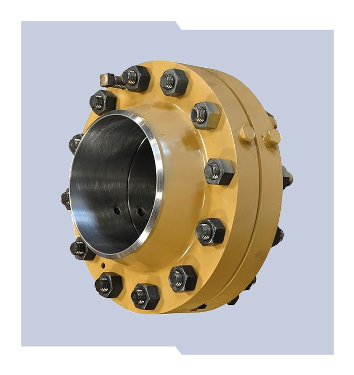
Orifice Flange Unions
Quality Beyond Compare
EExceptional performance and superior durability are the hallmarks of Daniel Orifice Flange Unions. Available in line sizes 2-inch to 8-inch and ANSI 600 to 2500 with carbon steel or stainless steel assembly. Every Daniel OFU is expertly manufactured to meet or exceed AGA 3/API 14.3 standards.
Coming Soon:
| Mechanical Ratings | Standard: 2-in to 8-in, ANSI 600-2500
Consult factory for other options |
| Flange Face And End Connections | Standard: Raised face weldnek and ring-joint weldnek |
| Assembly | Carbon Steel: furnished complete with studs (ASTM A-193 GR B7), nuts (ASTM A-194 GR 2H), (2) 0.0625-in non-asbestos gaskets and (2) jackscrews
Stainless Steel: furnished complete with zinc plated studs (ASTM A-193 GR B7), nuts (ASTM A-194 GR 2H), (2) 0.0625-in non-asbestos gaskets and (2) jackscrews |
| Differential Pressure Taps | Location and number of tap holes
Process connection
Types of tap connections
Line bore tolerances
|
| Temperature Range | Standard: -20°F to +250°F (-29°C to +121°C)
Standard (low temperature): -100°F to +250°F (-73°C to +121°C) Consult factory for other options |
| Material Specifications | Standard: A105 Carbon Steel and A350 LF-2 (low temperature applications)
Consult factory for other options |
| Flow Measurement Code | API 14.3
ISO-5167 |
| Design Code | ASME B16.36 |
| Gaskets | Standard gaskets for RF flanges are 0.625-in thick. (0.125-in thick gaskets are available as an option.)
RTJ Flanges use Daniel model 560 or 590 style plate holders. The plate holder is designed with an equivalent ring gasket to match the R-number based on size and pressure class. |
- Bore Tolerances are well within the latest recommendations of API-14.3.
- Pressure Tap Hole Location is closely controlled. Tap hole centers are 0.938-in from bearing faces of raised face flanges, placing their centerline 1-in from the face of the orifice plate when 0.063-in gasket thickness is included.
- 1. For 3-in and smaller flanges, tap location tolerance is ± 0.016-in.
- 2. For 4-in and larger flanges, tap location tolerance is ± 0.031-in.
- Pressure Tap Holes – Tap hole edges on the flange bore surface are carefully inspected to be free from burrs. All roughness is eliminated. Sizes are shown in the following tables.
- Flange Tap Connections – Standard connections are .50-in NPT. Other sizes and types are available on request.
- Gaskets – Two 0.063-in thick(1) precision die-cut gaskets are furnished with all raised face orifice flanges. Non-asbestos gaskets are standard.
- Dowel pins: Alignment dowel pins of the knock-out type are furnished as standard on all 2-in to 8-in raised face orifice flanges. These dowel pins assure correct alignment of the flange bores as well as centering the orifice plate bore to the flange bores within the tolerances of API-14.3.
| Line Size | DN50 to DN200 (2-in to 8-in) |
| Fluid Type | Liquid |
| Operating Temperature Range | -29º C to +66º C (-20º F to +150º F) |
| Operating Pressure Range | ANSI 150 to 300 |
| Materials: Valve Body | Carbon Steel, ASTM A352 GR LCC |
| Materials: Valve Cylinder | DN50 to DN 200 (2-in to 4-in): Stainless Steel, ANSI 150 to 600; DN250 to DN 300 (6-in to 8-in) Carbon Steel, Nickel Coated, ANSI 150 to 600 |
| Materials: Valve Piston | Standard: Stainless Steel |
| Materials: Seat Ring | DN50 to DN200 (2-in to 6-in) Stainless Steel; DN300 (8-in) Carbon Steel, Nickel Coated |
| Materials: O-Rings | Standard: Viton; Optional: Neoprene, EPR, Kalrez / Teflon AP (Aggressive Products) |


